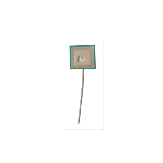
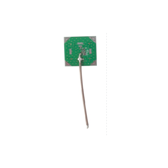
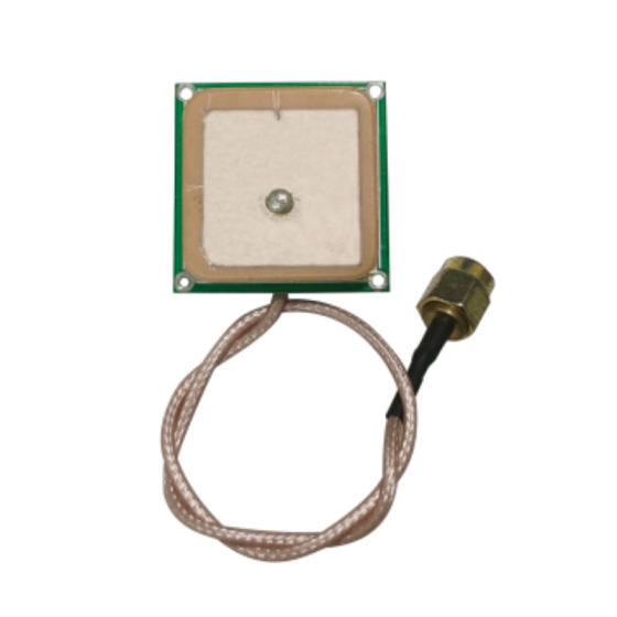
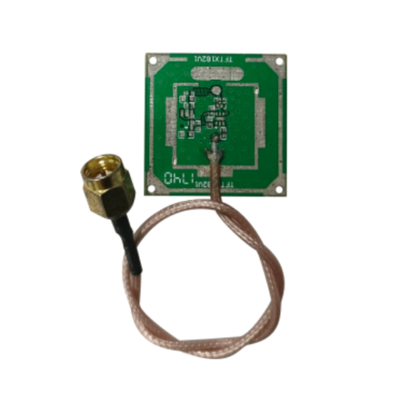
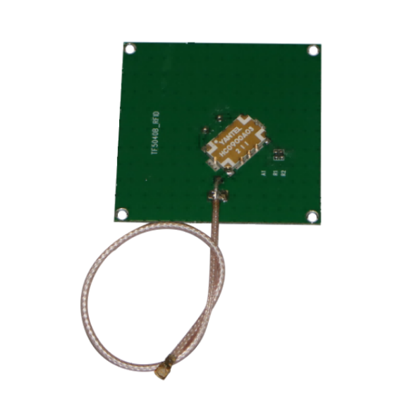
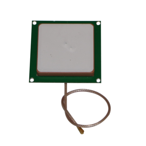
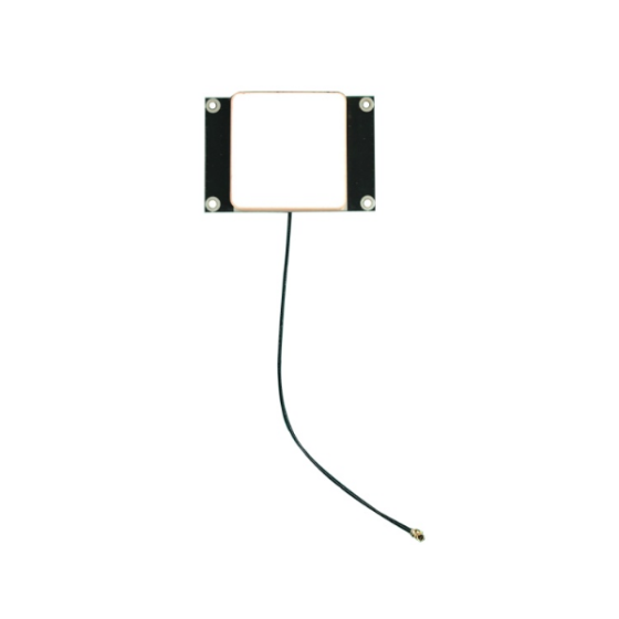
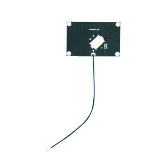
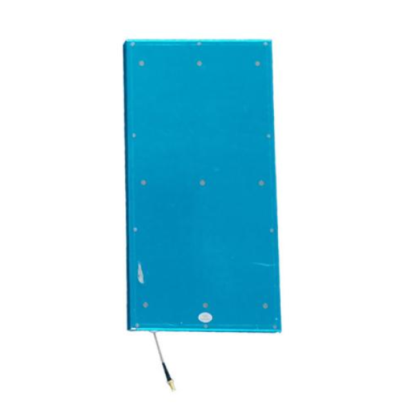
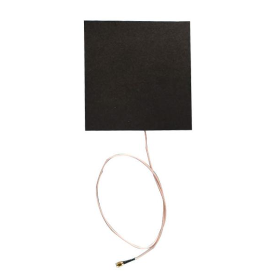
The 10dBi Circularly Polarized PCB Antenna is designed for 902–928MHz UHF RFID systems that require stable tag identification, directional coverage, and reliable RF performance. With a 10dBi gain and circular polarization, the antenna can help maintain consistent RFID tag reading even when tags are positioned at different angles.
Featuring a 50Ω impedance, VSWR of ≤1.3, and an SMA connector, this antenna can be integrated into a variety of UHF RFID readers and identification systems. Its 380 × 190 × 20mm compact structure makes it suitable for indoor RFID installations where controlled and directional coverage is required.
The antenna is suitable for applications including personnel management, asset tracking, access control, and vehicle management.
Product Applications
The 10dBi circularly polarized antenna can be used in a variety of UHF RFID identification and tracking applications.
Personnel Management
Use the antenna with UHF RFID systems to support personnel identification and movement management at designated reading points.
Asset Management
The antenna can be integrated into RFID asset tracking systems to help identify tagged equipment, tools, inventory, and other physical assets.
Access Control
Combined with an RFID reader and RFID tags, the antenna can be used in access control systems to identify authorized personnel or tagged objects.
Vehicle Management
The antenna can be installed at vehicle identification points to support RFID-based vehicle tracking and management.
Typical RFID System Configuration
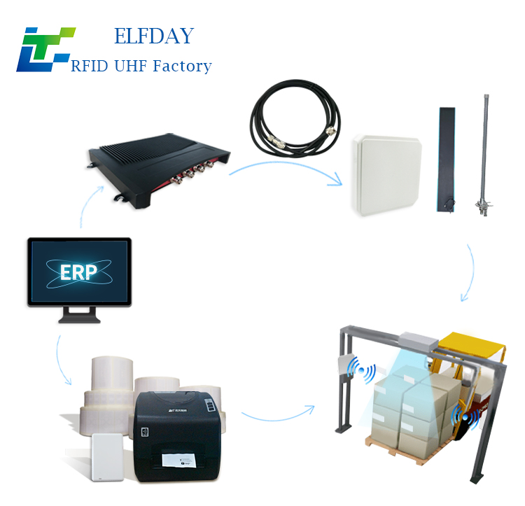
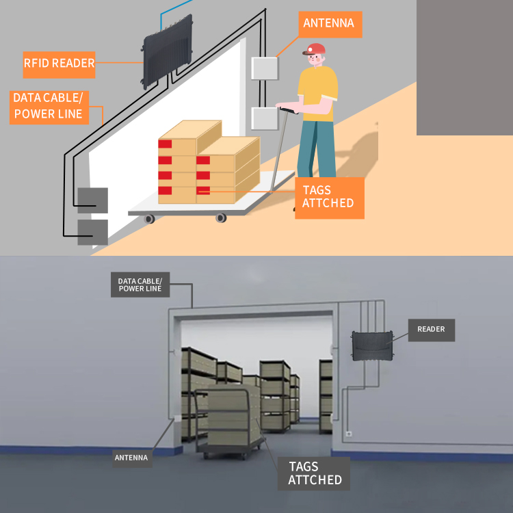
A complete RFID identification system can consist of:
UHF RFID Tag → RFID Antenna → RFID Reader → Software / Management Platform
The antenna communicates with RFID tags through radio frequency signals and connects to the RFID reader through its SMA interface. The reader then processes the tag information and transfers the data to the relevant management software.
Radiation Characteristics
The antenna provides a horizontal beamwidth of approximately 45° and a vertical beamwidth of approximately 80°. This directional coverage makes it suitable for installations where the RFID reading area needs to be controlled.
The front-to-back ratio is ≥20dB, helping reduce unwanted radiation from the rear of the antenna and supporting more controlled RF coverage.
Technical Specifications:
| Electrical specifications |
| Product Type |
Circularly Polarized PCB Antenna |
| Application |
UHF RFID |
| Frequency Range |
902–928MHz |
| Gain |
10dBi |
| Polarization |
Circular Polarization |
| Horizontal Beamwidth |
45° |
| Vertical Beamwidth |
80° |
| VSWR |
≤1.3 |
| Front-to-Back Ratio |
≥20dB |
| Impedance |
50Ω |
| Connector |
SMA |
| Lightning Protection |
DC Ground |
| Mechanical specifications |
| Antenna Dimensions |
380 × 190 × 20mm |
| Net Weight |
0.94kg |
| Radome Material |
Acrylic |
| Radome Color |
Black |
| Protection Rating |
IP64 |
| Installation Environment |
Indoor |
| Operating Temperature |
-20°C to 60°C |
Why Choose a Circularly Polarized RFID Antenna?
RFID tags are not always installed in exactly the same orientation. Depending on the application, tags may be placed horizontally, vertically, or at different angles.
A circularly polarized antenna can provide more flexibility for RFID deployments where tag orientation is difficult to control. This can be particularly useful for asset tracking, personnel identification, vehicle management, and other applications involving moving or randomly positioned tags.
For installations requiring a defined reading zone, the 10dBi gain and directional beam pattern can also help focus coverage toward the intended RFID detection area.
Installation Considerations
For optimal RFID performance, antenna installation should be planned according to the required reading zone and surrounding environment.
-
Position the antenna toward the intended RFID reading area.
-
Keep the antenna away from large metal structures whenever possible unless the installation has been specifically designed for the environment.
-
Avoid placing multiple antennas too close together without appropriate RFID system configuration.
-
Select the antenna mounting position according to the expected tag orientation and movement direction.
-
Use a suitable 50Ω RF cable and compatible SMA connection.
-
Perform RFID reader and antenna configuration after installation to achieve the required reading performance.
Actual RFID reading distance and performance can vary depending on the RFID reader, tag type, tag orientation, cable loss, installation height, surrounding materials, and operating environment.
FAQ
What frequency does this RFID antenna support?
This circularly polarized antenna operates from 902 to 928MHz, making it suitable for compatible UHF RFID systems.
What is the antenna gain?
The antenna provides a 10dBi gain, with a horizontal beamwidth of 45° and vertical beamwidth of 80°.
Is this antenna circularly polarized?
Yes. The antenna uses circular polarization, which can be useful for RFID applications where tag orientation varies.
What connector does the antenna use?
The antenna uses an SMA female connector and has a nominal impedance of 50Ω.
Where can this antenna be used?
Typical applications include personnel management, asset management, access control systems, and vehicle management.
Can it be used outdoors?
The antenna has an IP64 protection rating, but the specified application environment is indoor use. For outdoor deployment, the actual installation environment and protection requirements should be evaluated before use.
What affects RFID reading distance?
RFID reading performance depends on multiple factors, including reader output power, RFID tag sensitivity, tag orientation, antenna installation position, cable loss, surrounding metal or other materials, and environmental conditions. Therefore, the actual reading range may vary between installations.
Product Summary
The 10dBi Circularly Polarized PCB Antenna provides a practical RF solution for 902–928MHz UHF RFID systems. Its 10dBi gain, circular polarization, directional beamwidth, low VSWR, 50Ω impedance, and compact PCB construction make it suitable for a range of indoor RFID identification and tracking applications.
It can be integrated into systems for personnel management, asset tracking, access control, and vehicle management, providing controlled RF coverage for applications where reliable RFID tag identification is required.