



What Is the Function of an RFID Antenna? How Should You Select an Antenna for an RFID System?
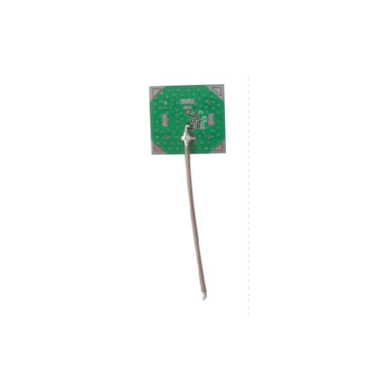
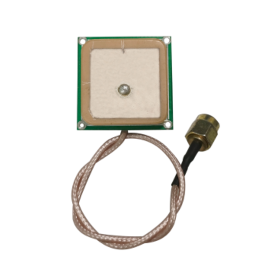
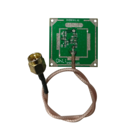
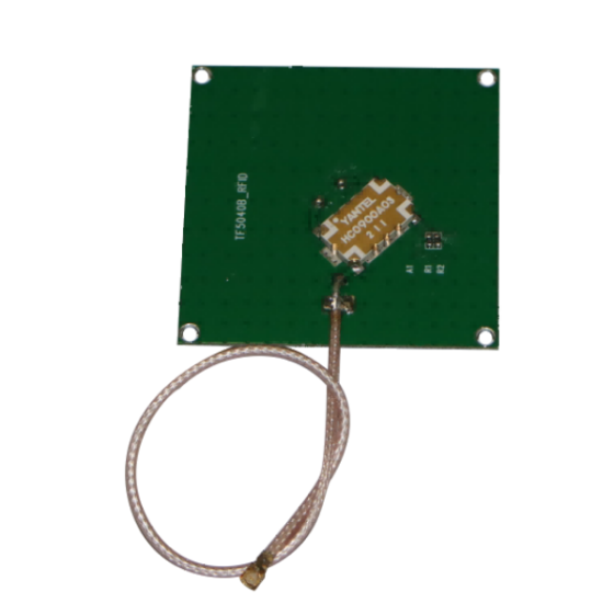
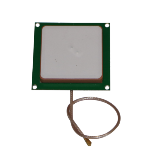
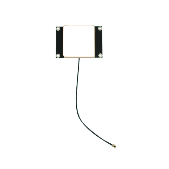
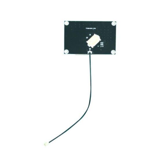
An RFID antenna is an essential component of many RFID systems. It enables radio frequency communication between an RFID reader and RFID tags by transmitting and receiving electromagnetic signals.
Although RFID readers generate and process radio frequency signals, antennas determine how those signals are distributed within the reading area. Their frequency, polarization, gain, beamwidth, and installation position can all influence tag identification performance.
Choosing the wrong antenna may result in insufficient coverage, unwanted reads, or inconsistent identification. Therefore, understanding the function of an RFID antenna and knowing how to select the right model are important steps in building an effective RFID system.
In this guide, we explain what an RFID antenna does, how it works, the common antenna types, and the key factors to consider when selecting an antenna for different RFID applications.
1. What Is an RFID Antenna?
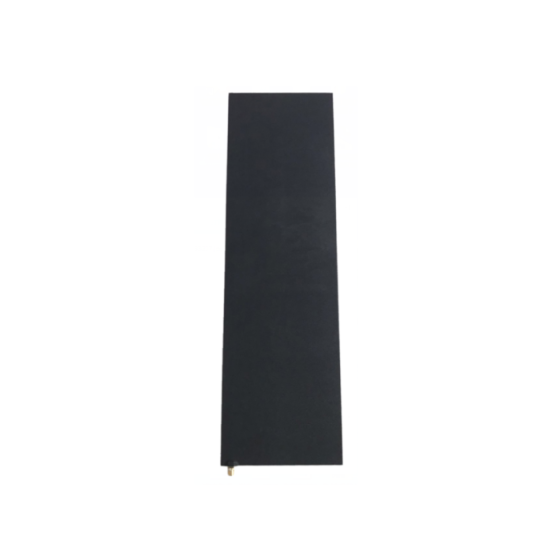
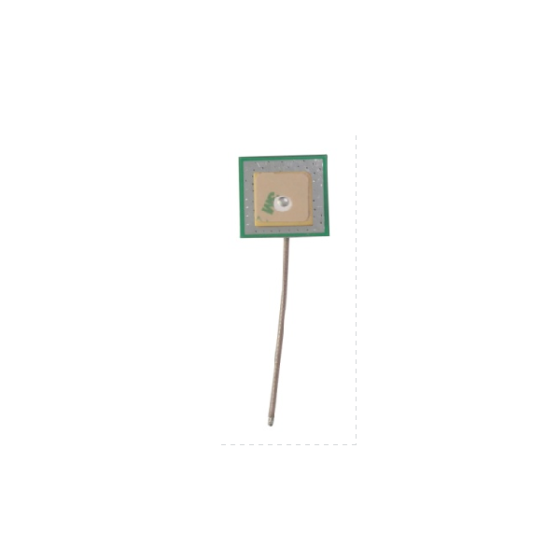
An RFID antenna is a device that transmits and receives radio frequency electromagnetic waves.
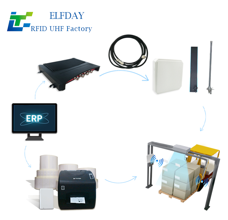
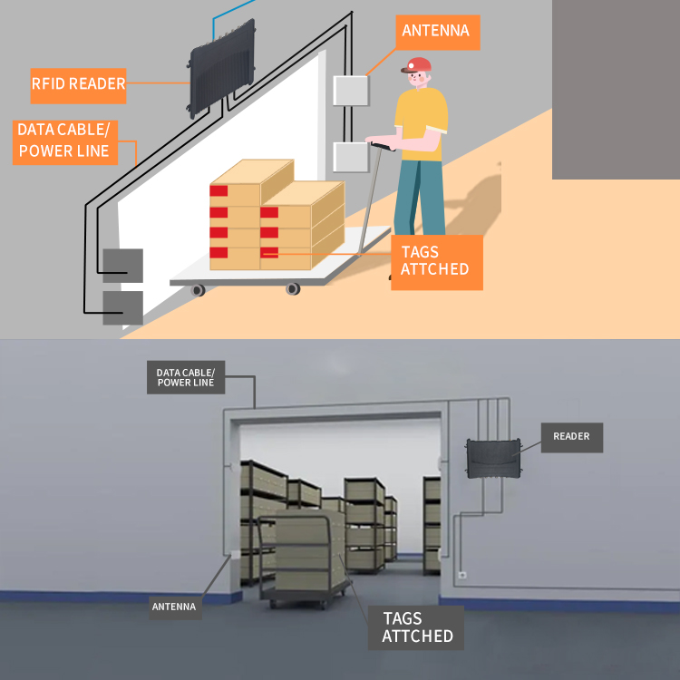
In a typical RFID system using an external antenna, the antenna connects to an RFID reader through an RF cable. The reader sends a signal to the antenna, which radiates the signal into the surrounding area.
When a compatible RFID tag enters the communication area, it can receive the reader's signal and respond. The antenna receives the tag's response and passes the corresponding RF signal back to the reader for processing.
The basic communication process is:
-
The RFID reader generates a radio frequency signal.
-
The antenna transmits the signal into the reading area.
-
The RFID tag receives the signal and responds.
-
The antenna receives the tag's response.
-
The RFID reader processes the received signal and identifies the tag.
This process allows RFID systems to identify tagged objects without requiring direct optical contact or line-of-sight scanning.
Some RFID readers have built-in antennas, while others support external antennas connected through RF ports.
2. What Are the Main Functions of an RFID Antenna?
An RFID antenna does more than transmit radio signals. Its design and installation influence how an RFID system communicates with tags.
2.1 Transmitting Radio Frequency Signals
The primary function of an RFID antenna is to transmit RF signals generated by the reader.
For passive RFID systems, the transmitted electromagnetic field provides the energy needed by compatible passive tags to operate and communicate.
The antenna's characteristics help determine how the RF energy is distributed within the intended reading area.
2.2 Receiving Signals From RFID Tags
After receiving the reader's signal, passive UHF RFID tags commonly respond through backscatter communication.
The tag changes the way it reflects the incoming RF signal, and the reader detects this modulated response.
The RFID antenna receives the returned signal and transfers it to the reader for decoding.
2.3 Defining the Reading Area
Antenna characteristics influence the shape and coverage of the reading area.
For example, a wide-beam antenna may cover a relatively broad area, while a narrower-beam antenna can concentrate energy in a more specific direction.
This is important for applications such as warehouse entrances, conveyor systems, and production stations, where the reading area needs to match the movement path of tagged objects.
2.4 Improving Tag Identification Consistency
A suitable antenna can help improve the consistency of tag identification when its frequency, polarization, gain, and mounting position match the application.
However, antenna selection alone cannot guarantee successful reads. Tag design, reader settings, object materials, tag orientation, cable loss, and environmental conditions also affect performance.
2.5 Supporting Multi-Tag Identification
In applications where multiple RFID tags need to be identified, antenna coverage helps determine which tags are within the communication area.
The RFID reader manages tag communication through the supported inventory protocol, while the antenna provides the RF link.
A properly designed antenna arrangement can help create suitable identification zones for cartons, pallets, products, or other tagged objects.
3. What Are the Common Types of RFID Antennas?
RFID antennas can be classified according to frequency, polarization, radiation characteristics, and application.
Understanding these categories helps businesses select an appropriate antenna for their systems.
3.1 UHF RFID Antennas
UHF RFID antennas are widely used in warehouse management, logistics, industrial automation, and asset tracking.
In many regions, passive UHF RFID systems operate within the 860–960 MHz range, with the specific permitted frequency bands depending on local regulations.
UHF antennas are available in different designs, including circular polarized, linear polarized, near-field, and directional antennas.
They are commonly used with compatible UHF RFID readers and tags.
3.2 HF RFID Antennas
HF RFID antennas typically operate at 13.56 MHz.
They are used in applications such as access control, NFC-related systems, library management, and close-range identification.
HF antenna designs are different from UHF antenna designs, so the reader, antenna, and tag must support compatible operating frequencies and protocols.
3.3 LF RFID Antennas
LF RFID antennas commonly operate at 125 kHz or 134.2 kHz, depending on the application.
They are used in selected applications such as animal identification, industrial identification, and access control.
LF antenna designs and communication characteristics differ from those of HF and UHF systems.
3.4 Circular Polarized RFID Antennas
Circular polarized antennas are commonly used in UHF RFID applications where tag orientation may vary.
They can help reduce sensitivity to rotational differences between the antenna and tag compared with a single linear polarization arrangement.
They are often considered for warehouse inventory, logistics, and conveyor applications involving items in different orientations.
3.5 Linear Polarized RFID Antennas
Linear polarized antennas generate an electromagnetic field with a defined polarization direction.
They can be suitable when the orientation of RFID tags is relatively consistent.
For example, if tags are mounted in a standardized position on products moving along a conveyor, a linear polarized antenna may be appropriate.
Correct alignment between the antenna and tag polarization is important.
3.6 Near-Field RFID Antennas
Near-field RFID antennas are designed for applications involving close-range identification.
They may be used at workstations, counters, document handling points, and other locations where tags are expected to be positioned relatively close to the antenna.
They can help create a more controlled identification area in suitable applications.
3.7 Directional RFID Antennas
Directional antennas concentrate radio frequency energy toward a particular direction.
They may be used at warehouse entrances, loading areas, production lines, and other locations where the reading area needs to be focused.
Their suitability depends on the required coverage, antenna positioning, and surrounding environment.
4. Key Parameters to Consider When Selecting an RFID Antenna
Choosing an RFID antenna requires evaluating several technical parameters rather than focusing on one specification.
4.1 Operating Frequency
Frequency compatibility is the first requirement.
The antenna must operate within the frequency range supported by the RFID reader and tags.
For example:
| RFID Frequency | Common Operating Frequency | Typical Applications |
| LF | 125 kHz / 134.2 kHz | Animal identification, selected industrial applications |
| HF | 13.56 MHz | Access control, NFC-related applications, library systems |
| UHF | Regional bands within approximately 860–960 MHz | Warehouse management, logistics, asset tracking |
A UHF RFID antenna cannot simply replace an HF antenna because their operating frequencies and antenna designs are different.
For UHF applications, the antenna's supported frequency range should also comply with the regulations in the installation location.
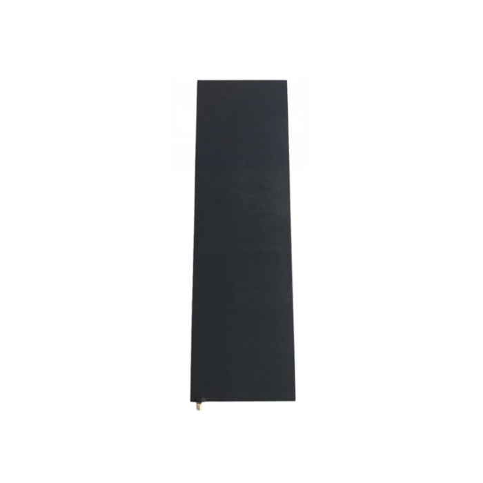
4.2 Antenna Gain
Antenna gain describes how effectively an antenna concentrates energy in a particular direction compared with a reference antenna.
It is commonly expressed in dBi.
Higher gain generally means a narrower radiation pattern for antennas with comparable designs, although the actual relationship depends on antenna construction.
A high-gain antenna may be useful when a more focused reading area is required.
However, higher gain is not always better. An antenna with excessive gain or an unsuitable radiation pattern may create unwanted reads or leave parts of the intended reading area insufficiently covered.
Select antenna gain according to the required coverage and system design.
4.3 Polarization
Polarization describes the orientation of the electromagnetic field radiated by the antenna.
The two common types used in UHF RFID applications are:
-
Circular polarization
-
Linear polarization
Circular polarization is often considered when tag orientation varies.
Linear polarization can be suitable when tag orientation is controlled and aligned with the antenna.
For example, a conveyor system with consistently positioned tags may use a linear polarized antenna, while a warehouse environment containing differently oriented cartons may benefit from circular polarization.
4.4 Beamwidth
Beamwidth describes the angular width of the antenna's radiation pattern, commonly measured at the half-power points.
It is generally specified in horizontal and vertical directions.
For example, an antenna specification may list:
-
Horizontal beamwidth: 65°
-
Vertical beamwidth: 35°
A wider beamwidth can provide broader angular coverage, while a narrower beamwidth concentrates energy within a more limited direction.
The appropriate beamwidth depends on the physical dimensions of the reading area, item movement, and antenna mounting position.
4.5 Impedance
Impedance matching is important for transferring RF energy efficiently between the reader, cable, and antenna.
Many UHF RFID systems use 50-ohm RF components.
The reader, antenna, and RF cable should have compatible impedance specifications to minimize signal reflections and avoid unnecessary losses.
4.6 VSWR
Voltage Standing Wave Ratio (VSWR) indicates how well an antenna is matched to its transmission line.
A lower VSWR generally indicates better impedance matching.
For example, an antenna specification of VSWR ≤ 1.5 indicates a relatively good impedance match within the stated operating conditions and frequency range.
When comparing antennas, check the VSWR specification across the entire frequency band required by the project.
4.7 Connector Type
The antenna connector must match the RF cable and reader interface.
Common connector types include:
-
SMA
-
N-type
-
TNC
-
Other manufacturer-specific RF connectors
Connector compatibility should be confirmed before purchasing.
Adapters can sometimes be used, but unnecessary connections may introduce additional loss and mechanical complexity.
4.8 Environmental Protection Rating
The antenna's protection rating should match the installation environment.
For example:
-
Indoor office applications may have relatively simple environmental requirements.
-
Warehouse applications may require protection against dust and occasional moisture.
-
Outdoor installations may require weather-resistant enclosures and connectors.
-
Industrial applications may require resistance to vibration, temperature changes, or other environmental conditions.
The antenna's IP rating and operating temperature range should be checked against the actual installation requirements.
5. How to Select an RFID Antenna for Different Applications
Different RFID applications require different antenna configurations.
The following examples illustrate how to approach antenna selection.
5.1 Warehouse Inventory Management
Warehouse inventory systems often involve cartons, pallets, shelves, and different tag orientations.
Recommended considerations include:
-
UHF RFID frequency compatibility
-
Circular or linear polarization according to tag orientation
-
Suitable gain and beamwidth for the reading zone
-
Mounting flexibility
-
Compatibility with fixed RFID readers
For example, circular polarized antennas may be considered at warehouse checkpoints where carton orientation varies.
5.2 Conveyor and Production Line Tracking
Conveyor systems require antennas that can identify tags as products or workpieces move through a designated area.
Important considerations include:
-
Tag orientation and mounting position
-
Conveyor speed
-
Antenna position
-
Reading zone dimensions
-
Nearby metal structures
-
Reader inventory settings
If tag orientation can be standardized, a linear polarized antenna may be suitable. If orientation varies, circular polarization may be worth evaluating.
Testing should be conducted with actual moving items rather than stationary samples alone.
5.3 RFID Access Control
RFID access control applications often require a clearly defined identification area near a doorway or access point.
Antenna selection should consider:
-
Required identification distance
-
Antenna coverage direction
-
Tag or credential orientation
-
Environmental conditions
-
Reader and credential compatibility
A controlled reading area is important to reduce the possibility of identifying credentials outside the intended access point.
5.4 Logistics and Shipping
Logistics applications may involve identifying tagged cartons, pallets, or reusable containers as they pass through loading and unloading areas.
Consider:
-
UHF RFID compatibility
-
Multi-tag identification requirements
-
Circular polarization where item orientation varies
-
Appropriate antenna coverage
-
Mounting positions around the passageway
Antenna placement should help identify the intended items while limiting unwanted reads from nearby storage or handling areas.
5.5 Metal Equipment and Industrial Assets
When RFID tags are attached to metal equipment, tag selection is particularly important.
The antenna itself does not automatically solve the communication challenges caused by mounting a standard RFID tag directly on metal.
Instead, the system should combine a suitable on-metal RFID tag with a compatible reader and antenna arrangement.
Antenna positioning and coverage should then be tested with the actual equipment and installation environment.
How Many RFID Antennas Does a System Need?
There is no fixed number of antennas required for every RFID system.
The number depends on the reading area, reader design, tag orientation, object movement, and required identification coverage.
Some applications use an integrated RFID reader with a built-in antenna. Others require multiple external antennas connected to a fixed reader.
For example:
| Application | Possible Antenna Configuration | Main Consideration |
| Small workstation | One integrated or external antenna | Controlled close-range identification |
| Warehouse entrance | Multiple external antennas | Coverage across the passageway |
| Conveyor system | One or more directional antennas | Identification of moving objects |
| Storage area | Multiple antennas across reading zones | Coverage and unwanted-read control |
| Mobile inventory | Built-in antenna in handheld reader | Portable identification |
Adding more antennas does not automatically improve system performance.
Antenna ports, reader capabilities, RF switching arrangements, installation positions, and the potential for interference between reading zones should all be considered.
Common Mistakes When Choosing an RFID Antenna
Selecting an antenna based only on price or advertised reading distance can lead to poor system performance.
Here are several common mistakes to avoid.
Choosing an Antenna With an Incompatible Frequency
An antenna must support the frequency band used by the RFID reader and tags.
Frequency mismatch can prevent the system from operating as intended.
Assuming Higher Gain Is Always Better
Higher gain may concentrate RF energy into a narrower area.
If the application requires broad coverage, a high-gain antenna may not be the best choice.
Ignoring Tag Orientation
The relationship between tag and antenna polarization affects communication.
If item orientation changes frequently, the antenna configuration should account for this variation.
Overlooking Installation Conditions
Metal structures, liquids, nearby equipment, and mounting surfaces can influence RF performance.
Testing in an actual operating environment is important.
Ignoring Cable Loss
Long or unsuitable RF cables can introduce signal loss between the reader and antenna.
Cable length, attenuation, impedance, and connector compatibility should be considered together.
Failing to Control Unwanted Reads
An antenna with unsuitable beamwidth or positioning may identify tags outside the intended reading zone.
Antenna placement and reader settings should be adjusted to match the required identification area.
RFID Antenna Selection Checklist
Before purchasing an RFID antenna, review the following specifications:
| Selection Parameter | What to Check |
| Frequency range | Must match the reader and tag frequency |
| Gain | Suitable for the required coverage |
| Polarization | Circular or linear according to tag orientation |
| Beamwidth | Appropriate horizontal and vertical coverage |
| Impedance | Compatible with the reader and RF cable |
| VSWR | Check matching performance across the operating band |
| Connector | Compatible with the RF cable and reader |
| Size | Fits the available installation space |
| Mounting method | Suitable for the installation structure |
| Protection rating | Matches indoor, outdoor, or industrial conditions |
| Operating temperature | Suitable for the working environment |
| Cable requirements | Appropriate length, attenuation, and construction |
An RFID antenna is responsible for transmitting radio frequency signals to RFID tags and receiving their responses. Its technical characteristics influence the communication area, tag orientation requirements, and overall identification performance of an RFID system.
When selecting an RFID antenna, businesses should evaluate frequency, gain, polarization, beamwidth, impedance, VSWR, connector type, environmental protection, and installation conditions.
The best antenna is not necessarily the one with the highest gain or the longest advertised reading distance. It is the antenna whose specifications and radiation characteristics match the actual application.
EFLDAY provides RFID antennas and related RFID products, including RFID tags and readers, for warehouse management, logistics, industrial automation, and asset tracking applications. Selecting compatible tags, readers, and antennas is an important step toward building a reliable RFID identification system.
Frequently Asked Questions
What is the main function of an RFID antenna?
An RFID antenna transmits radio frequency signals from the reader to RFID tags and receives the responses returned by compatible tags. It helps establish the communication area used for tag identification.
What is the difference between a circular polarized and linear polarized RFID antenna?
A circular polarized antenna is often used when tag orientation varies, while a linear polarized antenna can be suitable when tag orientation is controlled and aligned with the antenna. The appropriate choice depends on the application and installation conditions.
Is a higher-gain RFID antenna always better?
No. Higher gain generally produces a more concentrated radiation pattern for comparable antenna designs. The appropriate gain depends on the required coverage, reading distance, and surrounding environment.
How many antennas can one RFID reader support?
The number depends on the reader's antenna ports and supported configuration. Some readers have one port, while others support multiple external antennas. Additional antennas may require compatible RF switching equipment.
Can an RFID antenna read tags through metal?
An antenna cannot guarantee reliable communication with a standard RFID tag mounted directly on metal. Such applications generally require specially designed anti-metal RFID tags and appropriate system testing.
What frequency is commonly used for UHF RFID antennas?
Many UHF RFID systems operate within regional frequency bands in the approximately 860–960 MHz range. The exact supported band must match local regulations, RFID reader specifications, and tag compatibility.